Shielding effectiveness of a composite sphere
The accurate estimation of the electromagnetic field over a wide frequency band in composite material enclosures has a major importance with the generalization of the use of these materials in many domains like in aeronautics.
This capacity is compulsory in the context of lightning or HIRF environments to make an evaluation of the electromagnetic field at the equipment locations, or parasitic currents induced on the wiring.
In this context, We’ve been caught by a paper dealing with thin sheet modeling in FDTD. The paper is:
[1] “Face Centered Anisotropic Surface Impedance Boundary Conditions in FDTD” by IEEE members: D. Flintoft, S.A. Bourke; J.K Dawson, J. Alvarez, M.R. Cabello, M. P. Robinson and S. G. Garcia.
The paper introduces a new “Face Centered” formulation of anisotropic surface impedance.
AXS-E3, from AxesSim, comes as well with a BIBC implementation derived from the classical formulation. To us, it seems interesting to compare AXS-E3 and the “Face Centered” implementations.
With
What we use
CuToo is an efficient framework and a complete platform integrating simulation software products of a domain model in order to build a whole simulation tool for a given problem.
As an example, to leverage EMC issues, we use the following modules:
FreeCAD to design the model
MaxSim to mesh the model and generate the FDTD simulation
TEMSI-FD: it is our FDTD simulator (a cooperation with XLim)
Kawa to post-process and compare results
How
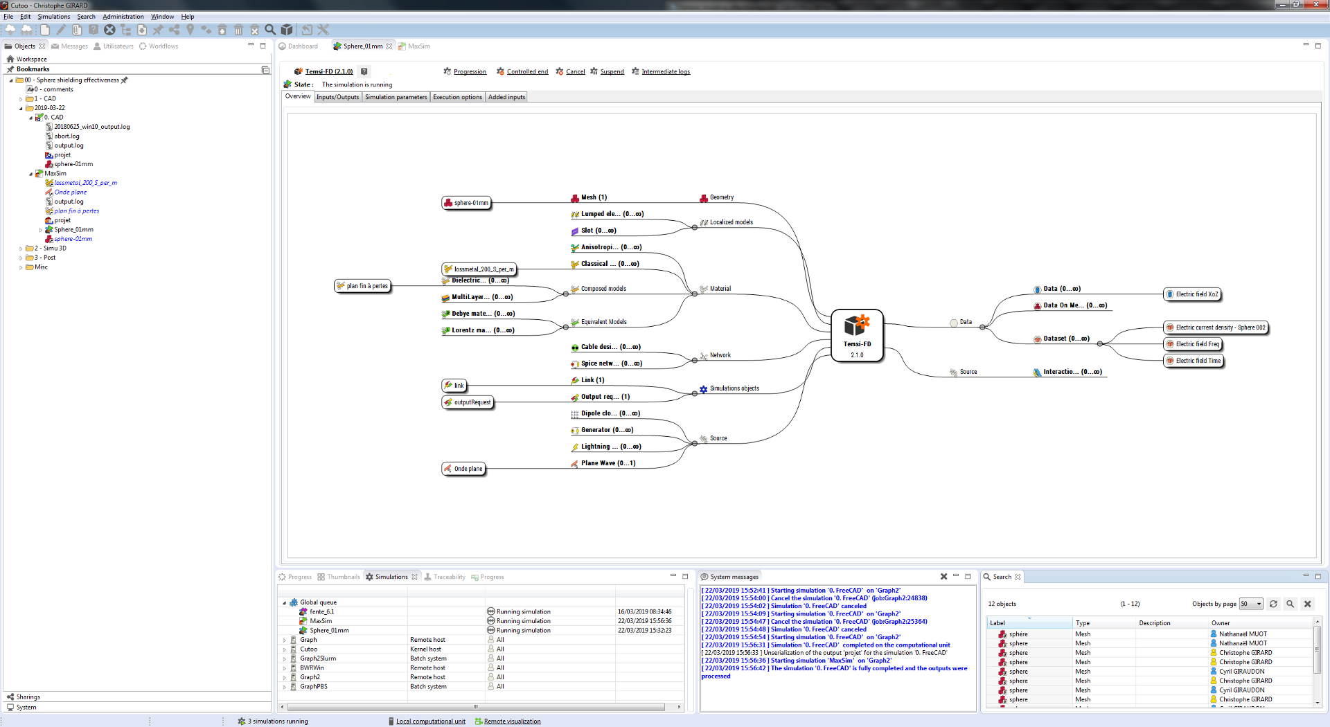
Modeling in CuToo
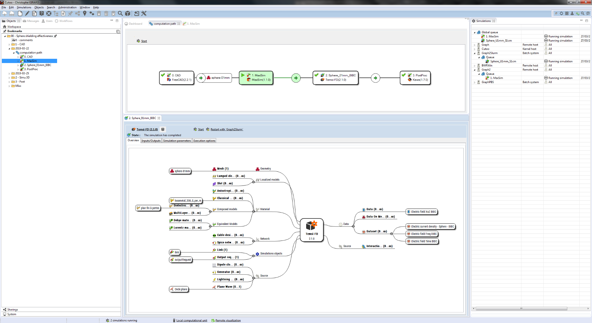
The various steps of the analysis are shown in the above figure:
The CAD model
The FDTD 3D simulation
The post-processing
Note: we can see in the preceding picture that CuToo can handle several batch queues managed by different batch job management.
So we simply draw a 1 meter radius sphere in FreeCAD located at (0, 0, 0).
With
FreeCAD
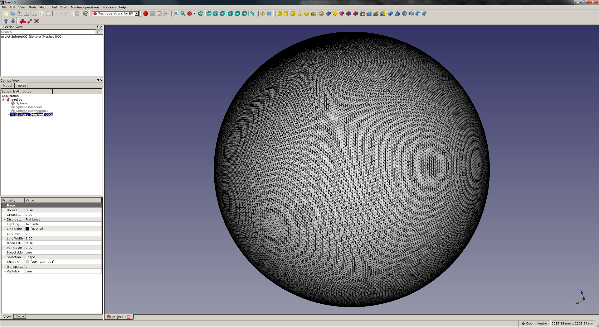
FreeCAD in CuToo can export a mesh in Amelet-HDF format, so that an unstructured mesh of the sphere is returned into CuToo and placed as an input of the MaxSim’s (simulation configurator) simulation.
With
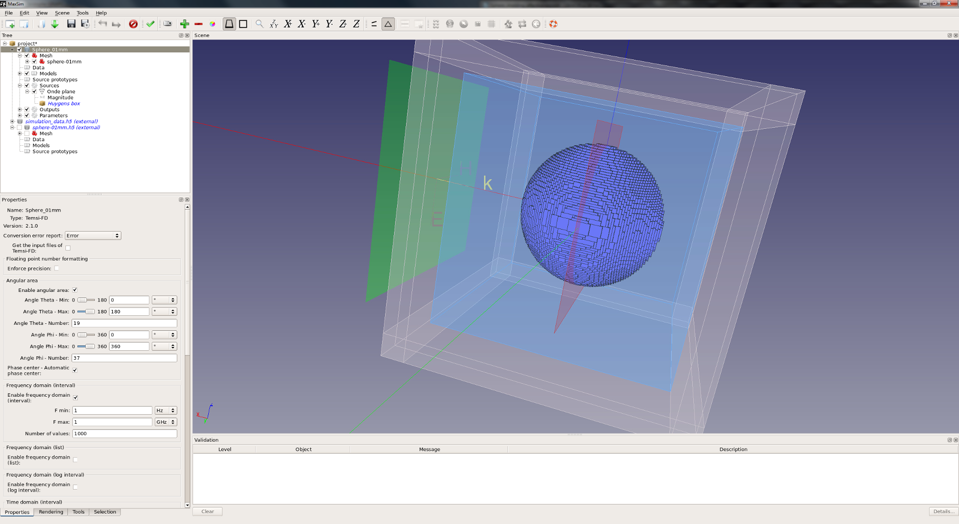
MaxSim
In MaxSim, a structured mesh is generated from the unstructured mesh.
In addition, a complete FDTD simulation is configured:
The boundary conditions : PML
A Huygens surface for the aggression : a plane wave
An output request : the electric field at the center of the sphere
With
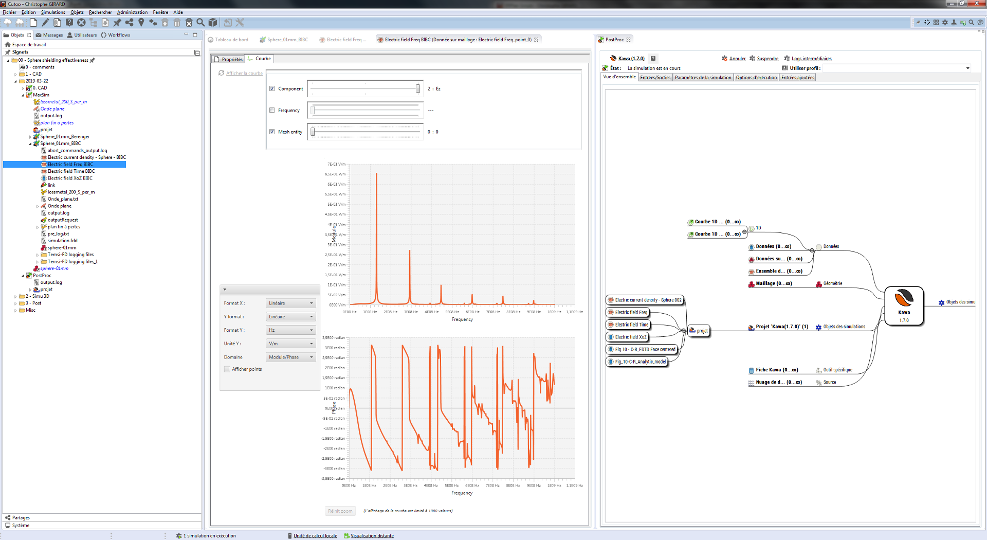
Back to CuToo
The simulation schematic can be visualized in CuToo:
The simulation has been submitted on 8 CPU and a few minutes later, we have been able to compare the results against the paper’s ones.
Before that, we picked some data in the paper and imported them in CuToo. See the data above the focused line in the picture hereafter:
With
KaWa
Four data have been compared:
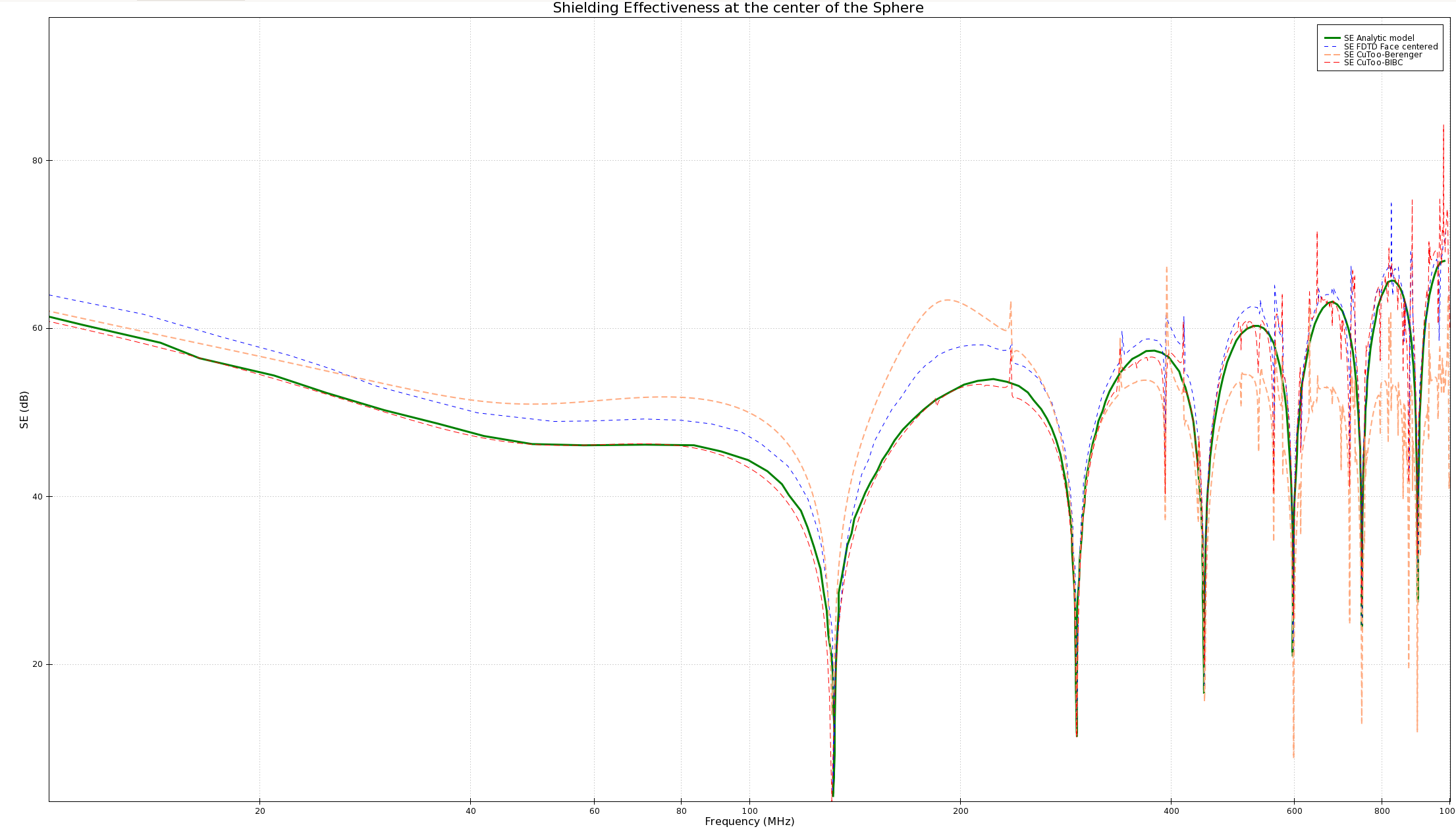
The analytic model (in green which is the reference)
“Face Centered” data from the paper (from [1])
Data computed in AXS-E3 for 2 different models :
- Berenger model (Low frenquency model) in orange
- BIBC model (wide band model) in red
We can see that the BIBC AXS-E3 results are the only ones that fit with the analytic model in the whole frequency range. In particular, in the law frequency range, the results of AXS-E3 are perfectly superposed with the reference result. On all the FDTD curves, we can see some small spikes that are generated by the stair-case effects of the mesh in the high frequency ranges. This effect has been observed and explained in [1].
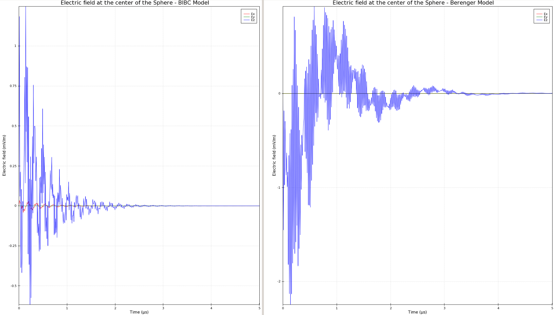
We take benefit of several models available in CuToo to analyze the differences observed in the results. Here above, we can notice the differences in time domain between Berenger and BIBC models at the center of the sphere. Waveforms are significantly different as well as component magnitude of the field.
Now
Discussion
The “face centered method” team had the good idea to compare the shielding effectiveness of the conductive sphere between a MoM stair-cased mesh and MoM smooth (conform) mesh.
Curves are very interesting and reported here-after:
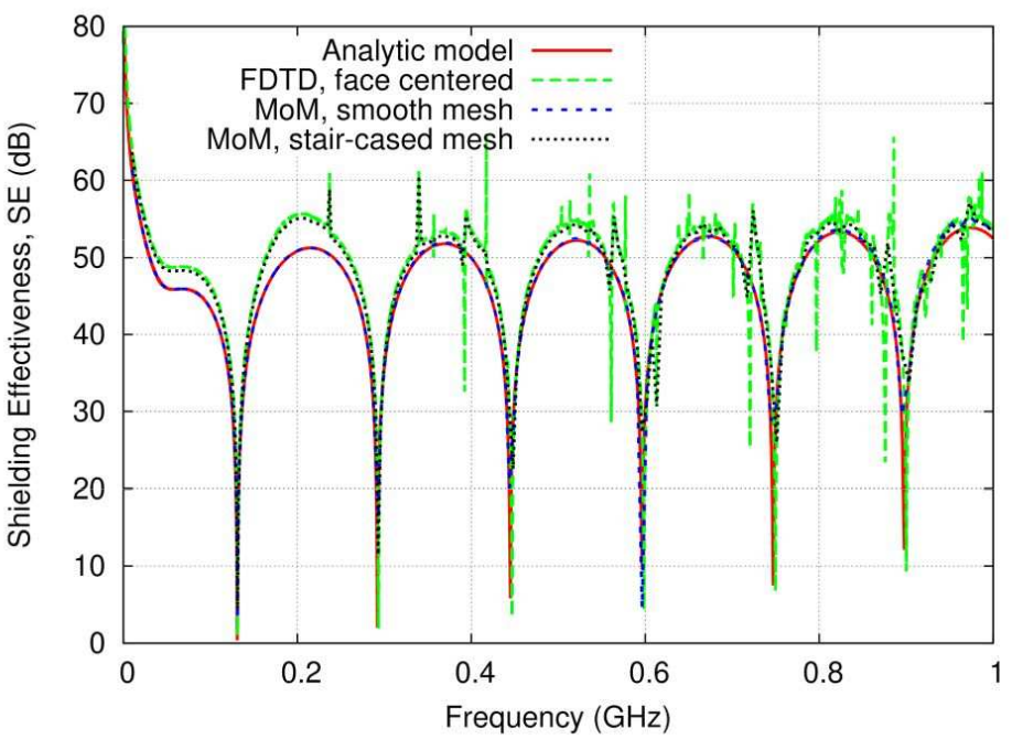
The faced centered method and the MoM stair-cased mesh model give comparable results, it is even clearer at low frequency. That is to say that a finer grid will not help to converge toward the reference but on the contrary a finer grid will help to converge toward the stair-cased model.
As we have noted above, at low frequency the AXS-E3 model converge toward the analytic model, so with AXS-E3 a finer grid will help to converge toward the reference.
Conclusion
AXS-E3 composite thin sheet model (BIBC) is the only one that allows to perfectly predict the level of internal field inside the sphere. This capability makes AXS-E3 a suitable, high-performance and accurate tool for the evaluation, in a wide frequency range, of electromagnetic fields penetrating into complex cavities.
This capability is essential in the context of lightning or HIRF environments in aeronautic industry, and AXS-E3 is perfectly suited for solving this type of problem.