
MaxSim
The Intelligent Environment for 3D Electromagnetic Simulation
An advanced modeling platform designed to streamline your workflow, from complex CAD preparation to high-performance solver execution

Why MaxSim ?
Maxsim is Axessim’s flagship simulation environment. It provides a unified platform to model complex EM systems, including Antennas and cable harnesses. With its intuitive interface and automated modeling aids, Maxsim drastically reduces model setup time while ensuring industry-grade precision.
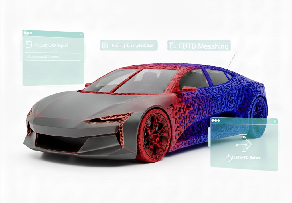
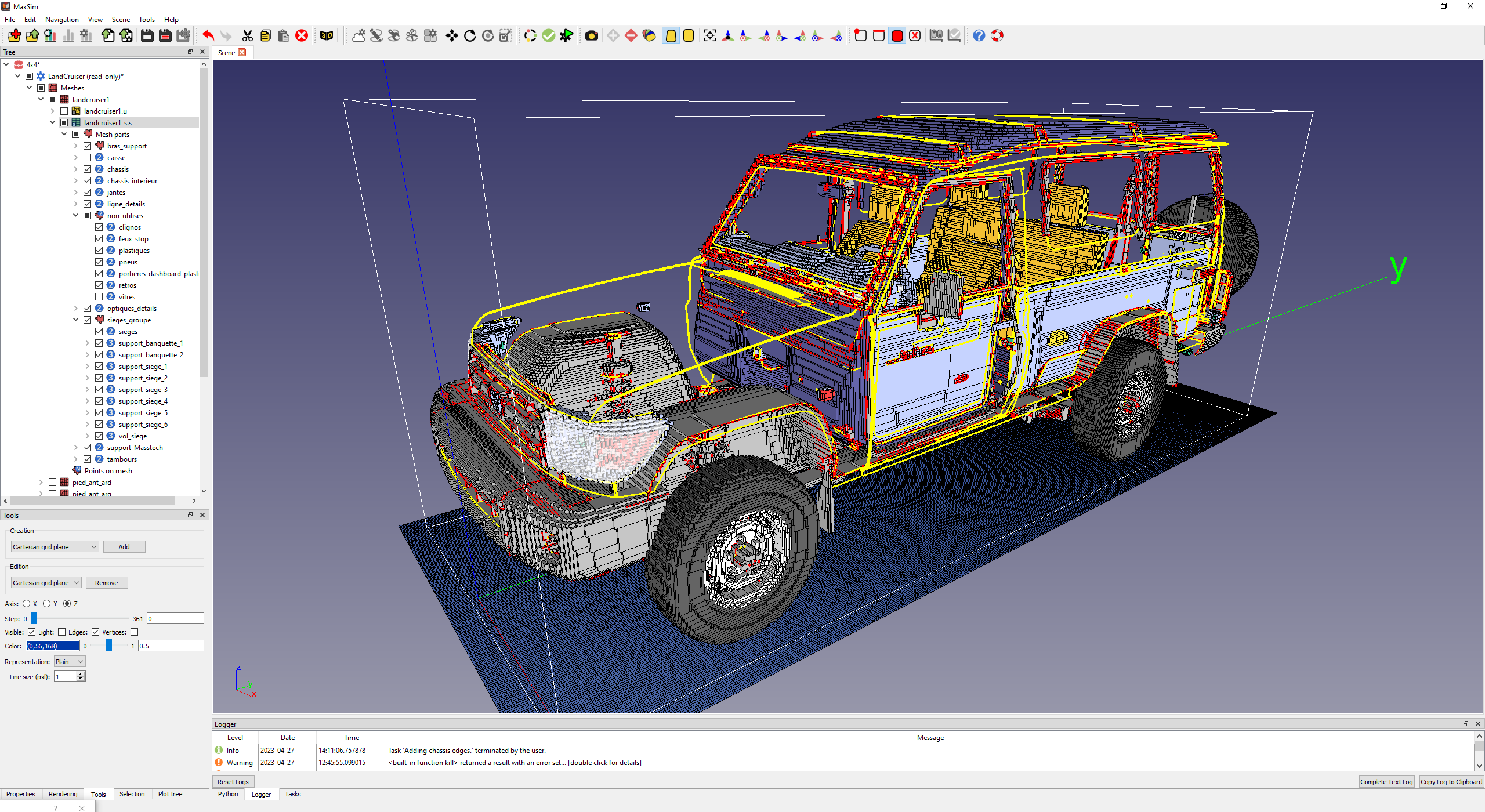
Geometric Modeling and CAD Import
Model Creation : In relation with FreeCAD (opensource 3D parametric modeler), create the 3D geometry of the device and its surrounding environment (air, vacuum)
Handling existing geometric data from the industrial process : Importation of existing models from CAD (Computer-Aided Design) software (e.g., STEP, IGES, … files)
Combination of multiple data sources to modelize complex simulation scenes
Geometry analysis and Simplification: Tools to fix errors, connectivity analysis, simplify complex parts that don’t affect the EM behavior
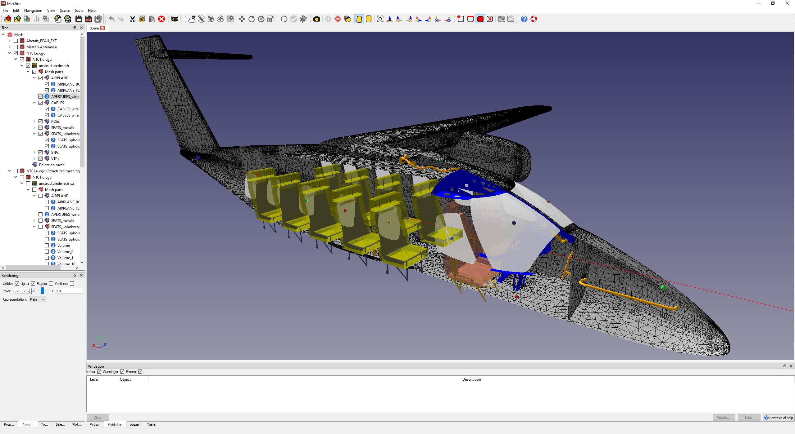
Hybrid Simulation
Configuring the simulation to handle complex scenarios where cable harnesses interact with larger 3D structures
MaxSim manages with CableSim the seamless coupling between the main 3D FDTD solver and the cable harness solver .
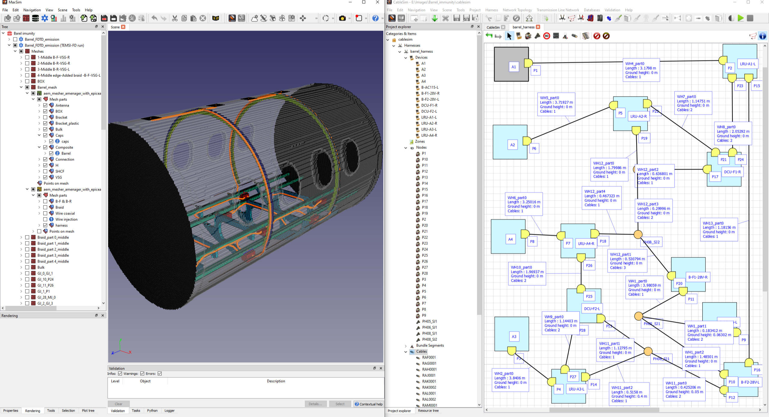
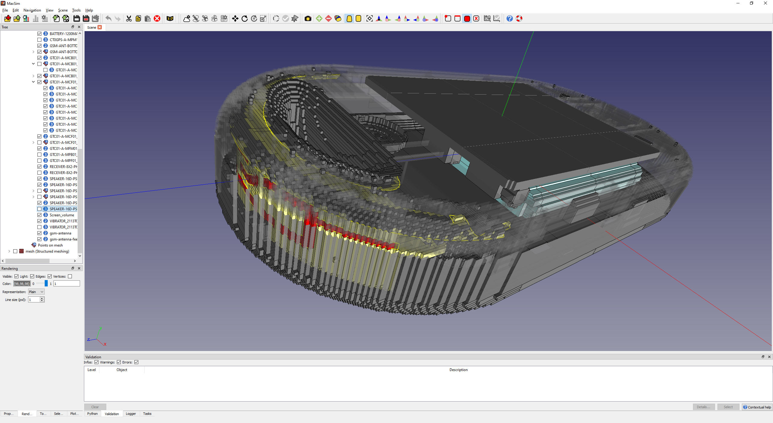
Mesh generation
Dividing the continuous 3D geometry into a finite number of smaller elements ( hexahedrons) necessary for numerical methods like FDTD.
High performance generation of structured meshes in orthogonal hexahedra
Flexible configuration, suitable for non uniform small and very large grids
Management of mesh life cycle
Benefits of hardware acceleration and High 3D rendering capabilities
Semi-automatic control to ensure meshes are meeting the expectations
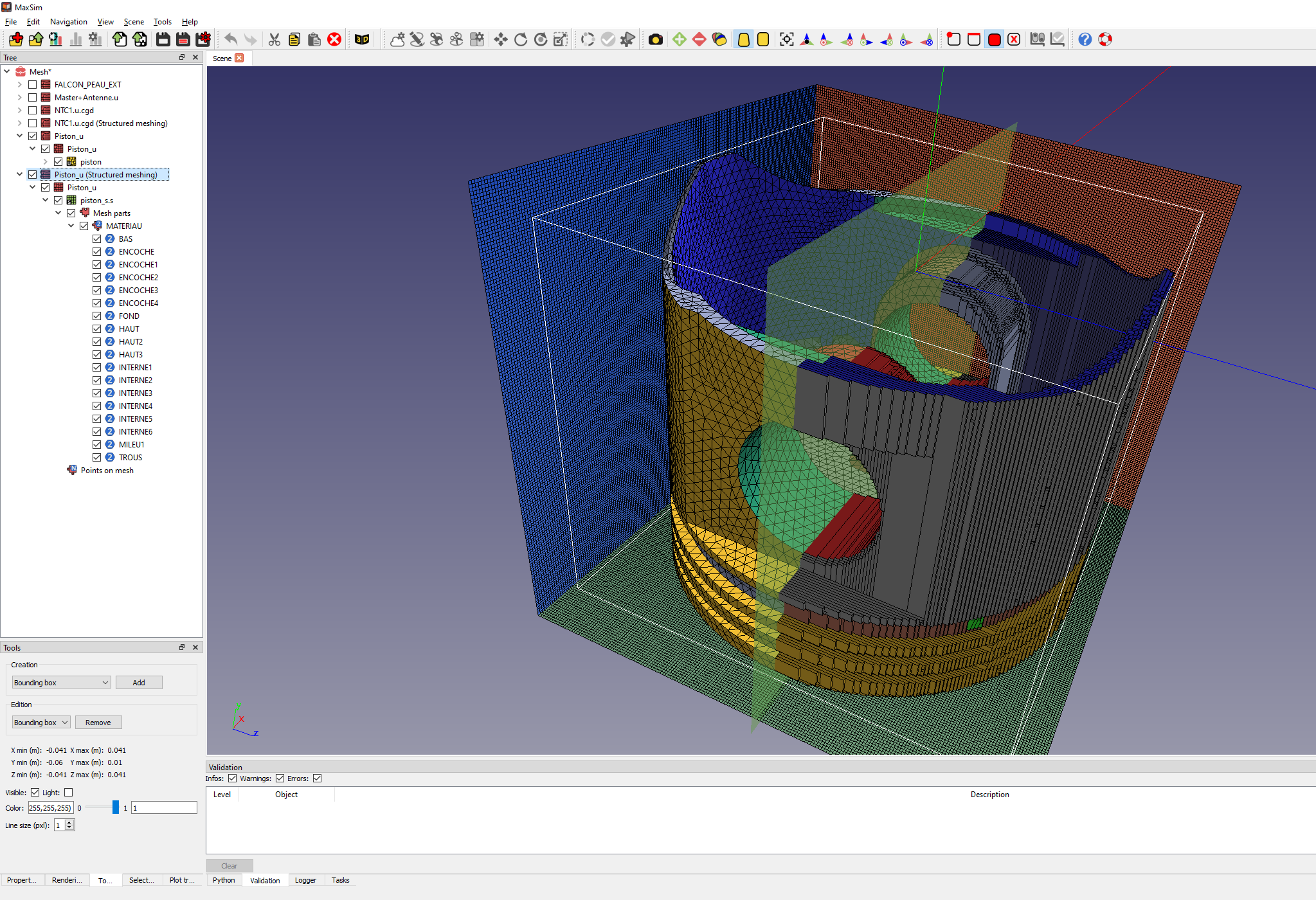
Mesh Control
Analysing and checking generated meshes for the FDTD numerical computation
Cleaning of imperfect structured meshes
Local interactive modifications of the mesh
Tools to detect hypothetical flaws (duplicated elements, holes detection, …) and electrical connectivity (free edges and connection edges, thin wire boundaries, …)
Number of elements reduction
Electromagnetic Models
Material definition and assignment:
Assigning the correct electromagnetic properties (ϵr (permittivity), μr (permeability), σ (conductivity)) to every part of the geometry
Complex Materials: Setting up advanced material behaviors, such as dispersive materials (frequency-dependent), anisotropic (direction-dependent) materials
Subcell models such as thin material plates, slots, gaskets, …
Cable / wire Properties
Specifying the wire diameter, insulation thickness, and the material properties (conductivity, permeability).
Routing and Interconnections: Defining the 3D path of the wires, including bends and how they connect to other components (e.g., connectors, ports, complex electric loads).
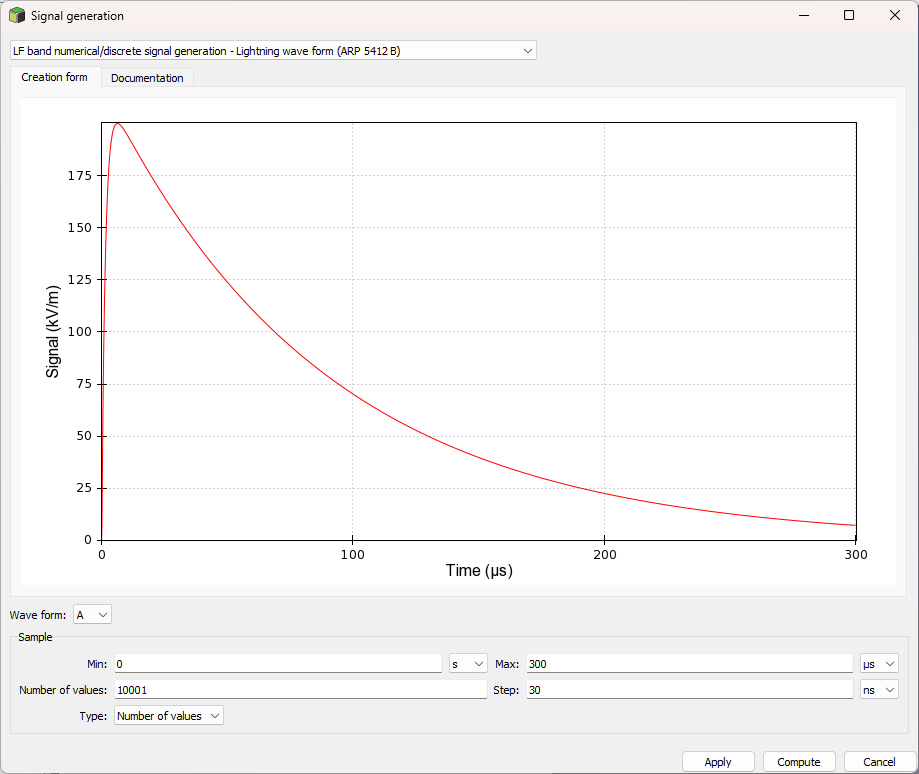
Sources/Excitations
Defining how energy is introduced into the system :
Lumped sources (voltage/current),
incident waves (plane waves),
Antenna models.
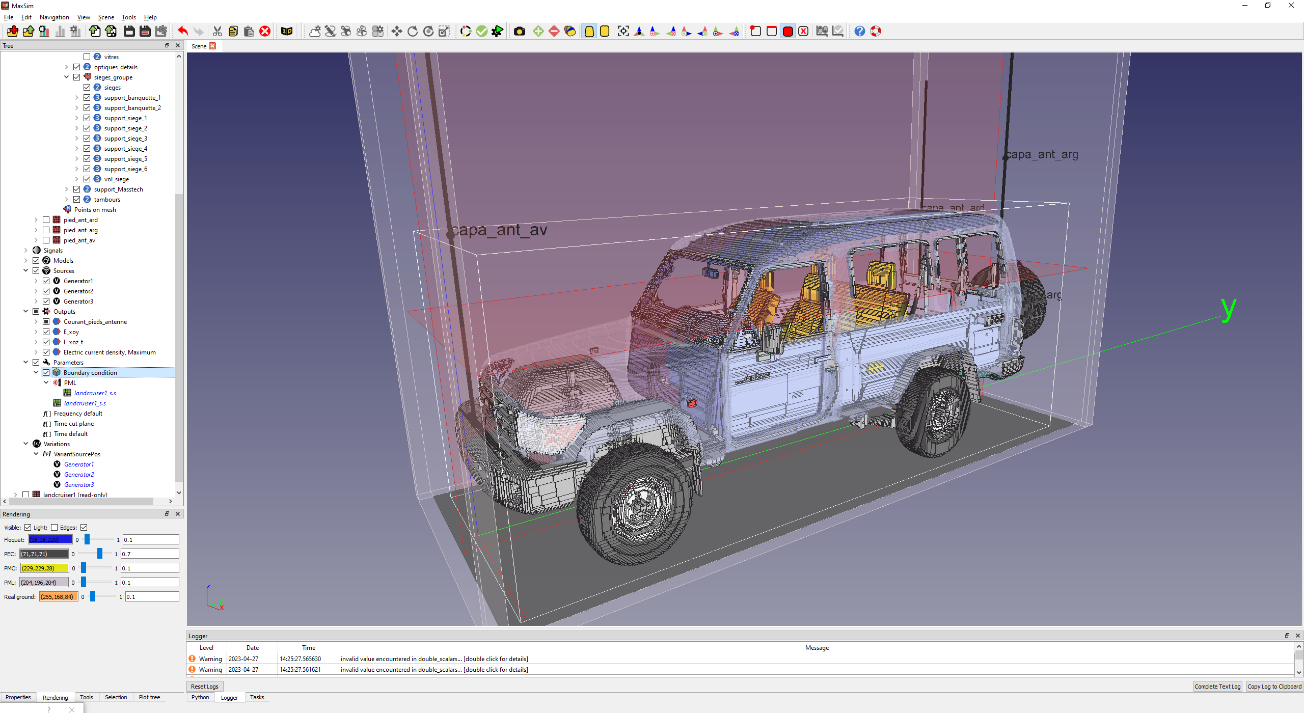
Boundary Conditions
Specifying the electromagnetic behavior at the limit of the simulation domain.
Perfectly Matched Layer (PML) to simulate infinite space and prevent reflections at the domain edges.
Perfect Electric Conductor (PEC) or Perfect Magnetic Conductor (PMC).
Stratified real ground
Visualization parameters
Radiated outputs (Electric and magnetic fields, radiated power, …) on localized probes or on virtual supports or surfacic parts of the structure
Conducted outputs (voltage, currents, power, …) on localized probes orsurfacic parts of the structure
Radiation patterns
Advance parametric study features
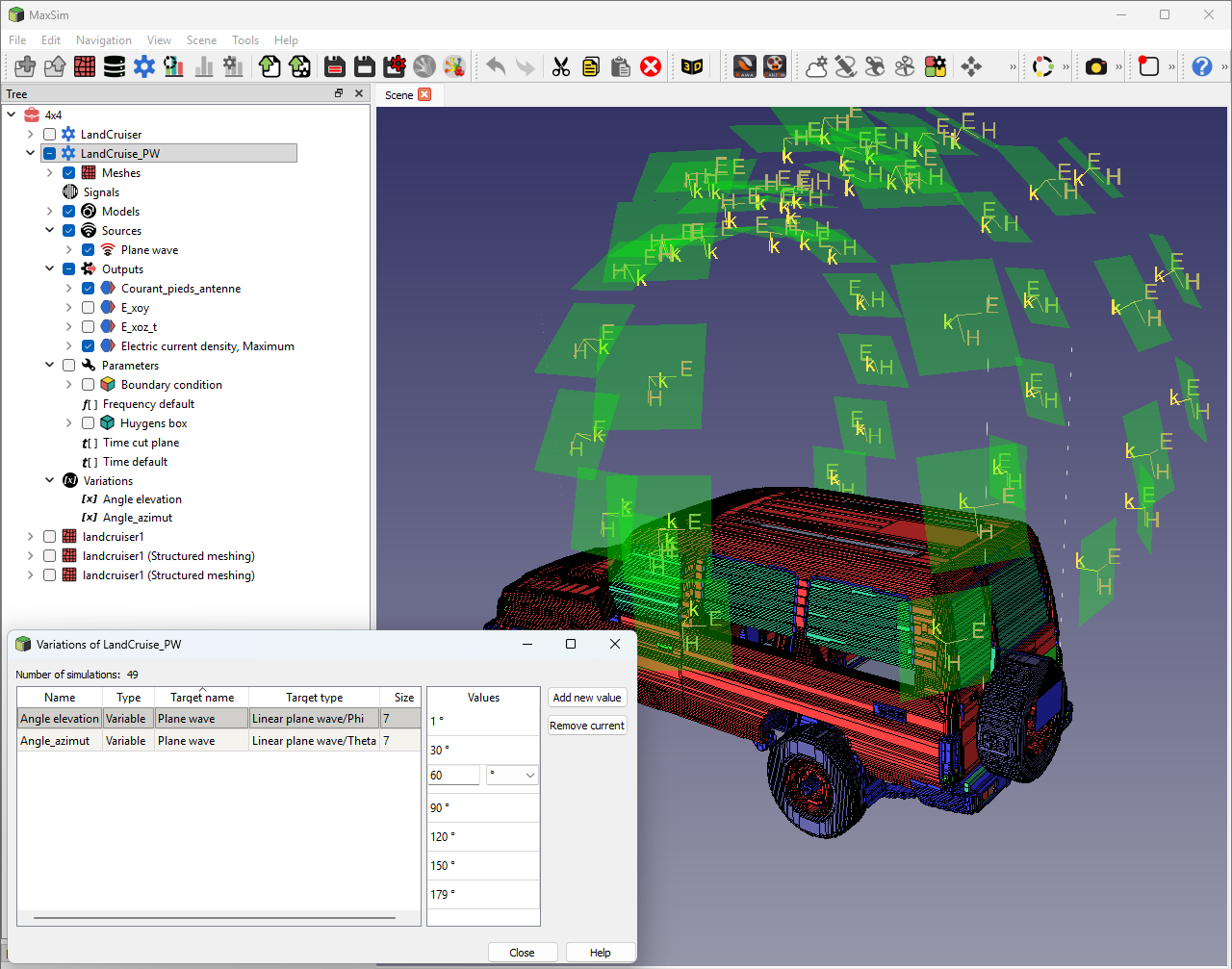
Parametric Analysis & Optimization
Maxsim does more than run a single simulation—it explores your entire design space.
Global Variables: Parameterize any dimension or material property with ease.
Parametric Sweeping: Launch automated simulation series to study the impact of specific variables.
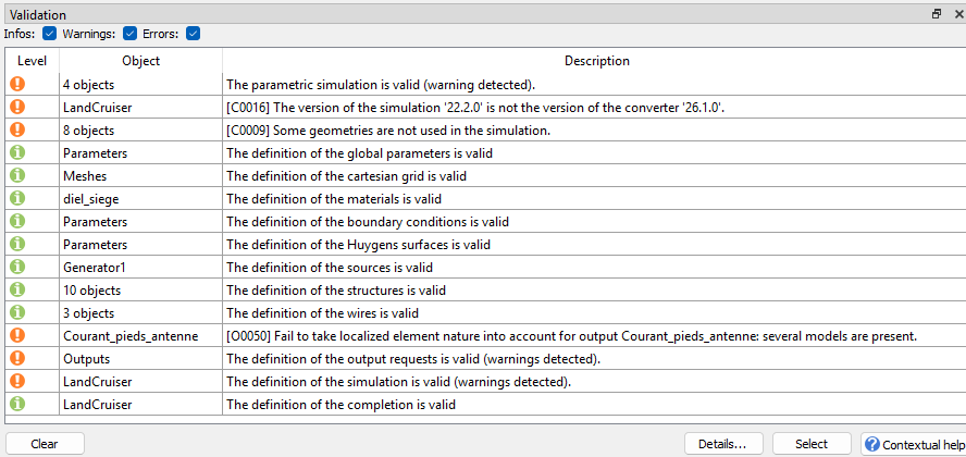
Validation framework
Validation framework based upon a rule engine : Geometric Validation, Connectivity Checks, EMC Rule Checking, numerical consistency of parameters (time and
frequency conditions, stability criterion, …)

TEMSI-FD is a software developed by XLim.
HPC FDTD solver
TEMSI-FD, a complete, powerful and versatile FDTD solver
Validated on numerous studies and industrial applications providing a full set of models required for EMC applications
Cosimulation with MTLN MILO solver in order to take into account the cable harness in its physical environment
HPC compatible : Intensive computation with Open-MP and MPI parallelism, Single and double precision
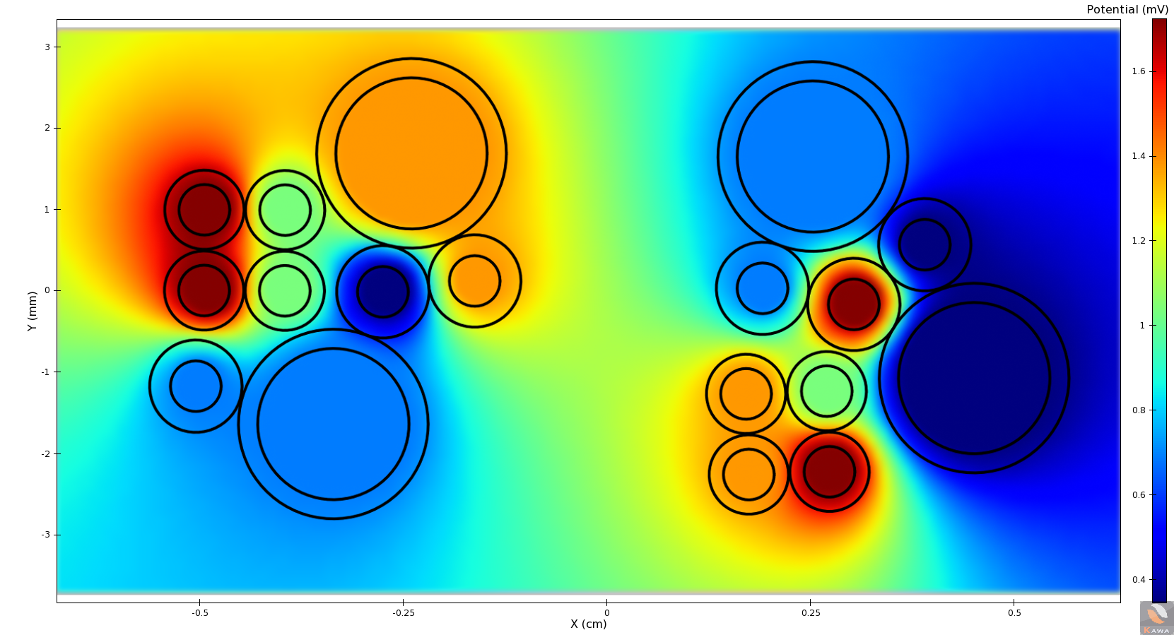
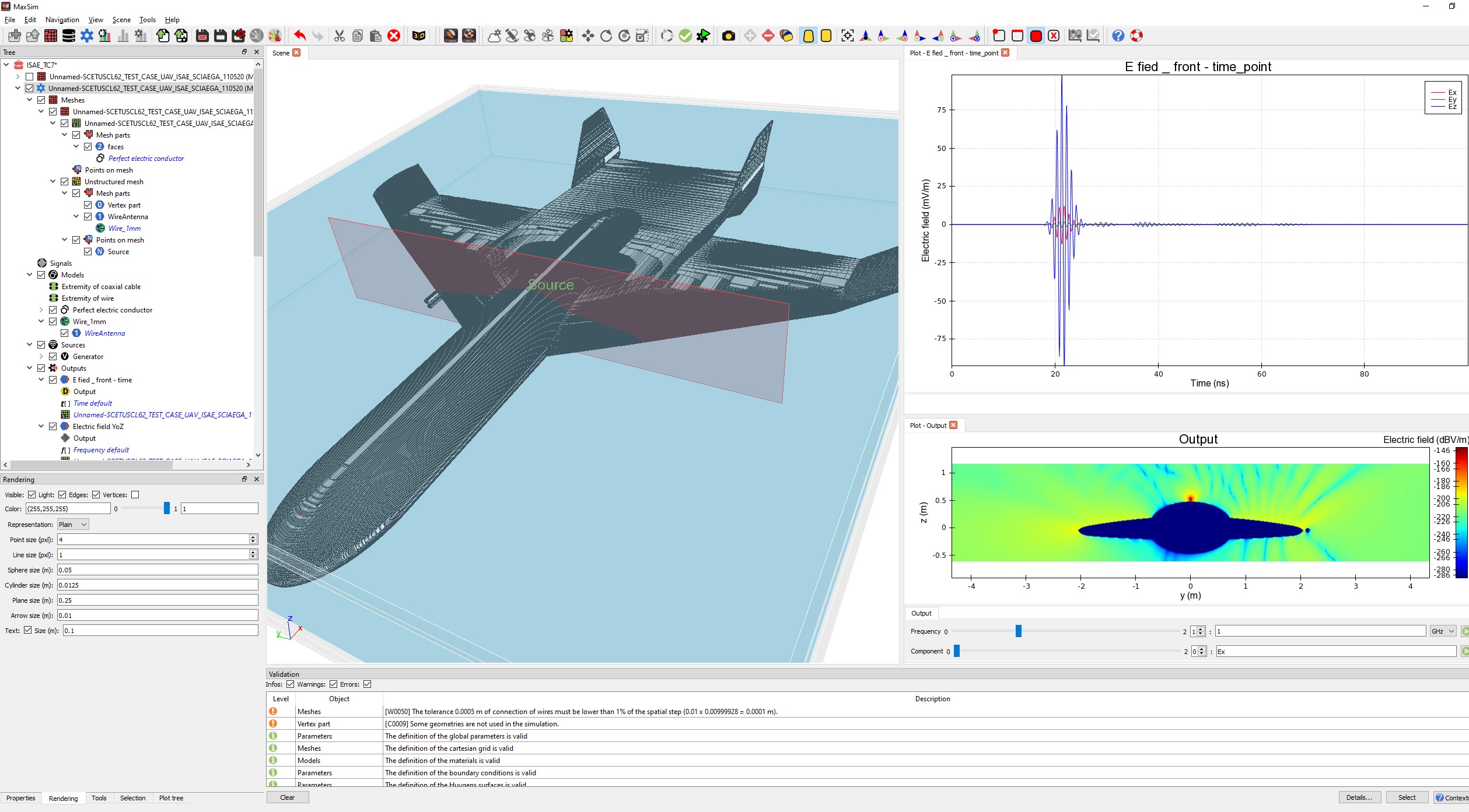
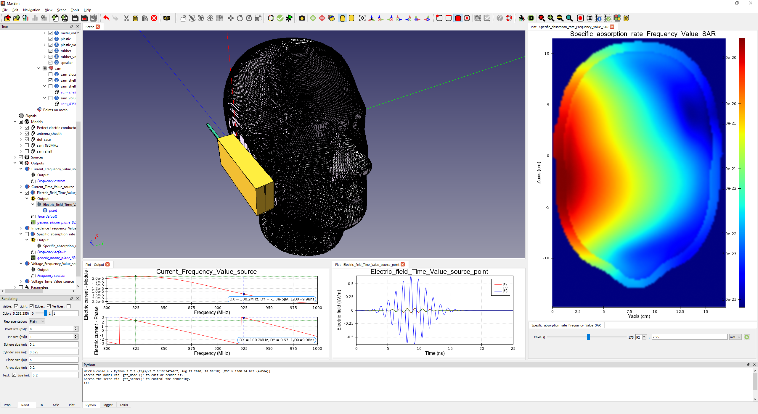
Preview of results
Pre-visualize results with a full set of plots allowing a quick and easy analysis before doing any post processing in Kawa software :
1D : Real and complex curves, Polar views, Histograms
2D: mappings and contours renderings.
The Maxsim Advantage
User-Centric Design:
A modern UI that flattens the learning curve for new engineers.
Scalability:
Equally capable of handling a single PCB component or a full-scale platform (naval ships, aircraft).
Unified Workflow:
Seamless transition from modeling in Maxsim and cableSim to post-processing in Kawa.