12. Networks and transmission lines
A transmission line is the material medium or structure that forms all or part of a path from one place to another for directing the transmission of energy, such as electromagnetic waves or acoustic waves, as well as electric power transmission. Components of transmission lines include wires, coaxial cables, dielectric slabs, optical fibers, electric power lines, and waveguides (http://en.wikipedia.org/wiki/Transmission_line).
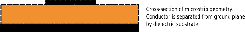
Some practical types of transmission lines are :
- Coaxial cable
- Microstrip
- Stripline
- Balanced line
12.1. Transmission line
In Amelet HDF Transmission lines are contained in the category
/transmissionLine. A
transmission line is a named HDF5 group.
This name most have less than 20 characters.
A transmission line is mainly defined by a cross section :
This cross section is described by an unstructured /mesh and
/physicalModel/ which are associated thanks to a dataOnMesh element.
Therefore, a transmission line group has three attibutes :
properties: it is an HDF5 group that contains the definitions of the distributed properties of the transmission line. This group has three exclusive set of children depending on thetypeattribute. Thetypeattribute can take the three following values :- If
typeequalsRLCG, the distributed properties are defined with the four matrix R, L, C and G. Thus,propertieshas four children :- R, R is a distributed resistance matrix
floatingTypedefined by :physicalNature=resistanceunit=ohmPerMeter
- L, L is a distributed inductance matrix
floatingTypedefined by :physicalNature=inductanceunit=henryPerMeter
- C, C is a distributed capacitance matrix
floatingTypedefined by :physicalNature=capacitanceunit=faradPerMeter
- G, G is a distributed conductance matrix
floatingTypedefined by :physicalNature=conductanceunit=siemensPerMeter
- R, R is a distributed resistance matrix
- If
typeequalsZY, the distributed properties are defined with the two matrices Z and Y Thus,propertieshas two children :- Z, Z is a distributed impedance matrix
floatingTypedefined by :physicalNature=impedanceunit=ohmPerMeter
- Y, Y is a distributed admittance matrix
floatingTypedefined by :physicalNature=admittanceunit=siemensPerMeter
- Z, Z is a distributed impedance matrix
- If
typeequalsZcGamma, the distributed properties are defined with the two matrix Zc and gamma Thus,propertieshas two children :- Zc, Zc is the characteristic impedance of the transmission and is
a distributed impedance matrix
floatingTypedefined by :physicalNature=impedanceunit=ohm
- gamma, gamma is the propagation constant per meter and has
one attribute :
physicalNature=propagationConstantunit=perMeter
- Zc, Zc is the characteristic impedance of the transmission and is
a distributed impedance matrix
- If
12.1.1. Properties types
Example of a transmission line data.h5:/transmissionLine/$tl1
with type = RLCG :
data.h5
`-- transmissionLine
    `-- $tl1
        `-- properties[@type=RLCG]
            |-- R[@floatingType=dataSet
            |     @physicalNature=resistance]
            |-- L[@floatingType=dataSet
            |     @physicalNature=inductance]
            |-- C[@floatingType=dataSet
            |     @physicalNature=capacitance]
            `-- G[@floatingType=dataSet
                  @physicalNature=conductance]
Example of a transmission line data.h5:/transmissionLine/$tl1
with type = ZY :
data.h5
`-- transmissionLine
    `-- $tl1
        `-- properties[@type=ZY]
            |-- Z[@floatingType=dataSet
            |     @physicalNature=impedance]
            `-- Y[@floatingType=dataSet
                  @physicalNature=admittance]
Example of a transmission line data.h5:/transmissionLine/$tl1
with type = ZcGamma :
data.h5
`-- transmissionLine
    `-- $tl1
        `-- properties[@type=ZcGamma]
            |-- Zc[@floatingType=dataSet
            |      @physicalNature=impedance]
            `-- gamma[@floatingType=dataSet]
12.1.2. Transmission line elements
Besides, a transmission line is made up of transmission line elements, those elements are conductors, shields ...
Example of a transmissione line data.h5:/transmissionLine/$tl1
with the element group
data.h5
`-- transmissionLine
    `-- $tl1
        |-- properties[@type=ZcGamma]
        `-- element                    # Transmission line element group
In Amelet HDF, elements are named HDF5 group children of the group
element and have five attributes :
type: it is an HDF5 string attribute that can take the following values :- if
type=conductor, the element is a conductor - if
type=shield, the element is a shield, a shield is a conductor reference for other conductor - if
type=dielectric, the element is a dielectric
- if
domain: thedomainreferences the shield domain.rank: This is the position of the element in the distributed properties matrixreferenceElement: This is the position of the reference conductor
A transmission line element has also an optional child :
properties: this is an HDF5 group, it contain the individual distributed properties for the element (in the case of a measurement for instance) and the transfer distributed properties relative to the shield conductor.propertieshas two string optional attributes :typeandtransferType.- if
type=RLCG,propertieshas four children R, L, C, G. This elements are defined as in the transmission line distributed properties, they represents the distributed properties of one element. - if
transferType=ZY, transfer distributed properties are defined by Zt and Yt. This elements are defined as in the transmission line distributed properties Z and Y, they represents the transfer distributed properties of one element. - if
transferType=RLCG, transfer distributed properties are defined by Rt, Lt, Ct and Gt. These elements are defined as in the transmission line distributed properties R, L, C and G, they represents the distributed transfer properties of one element.
- if
Example of a transmission line data.h5:/transmissionLine/$tl1 which have
two elements (the $ground and $elem1) :
data.h5
`-- transmissionLine
    `-- $tl1
        |++ properties
        `-- element
            |-- $ground[@type=conductor
            |           @domain=0]
            `-- $elem1[@type=conductor
                |      @domain=0
                |      @rank=1
                |      @referenceElement=$ground]
                `-- properties[@type=RLCG
                    |          @transfertType=ZY]
                    |-- Zt[@floatingType=dataSet
                    |      @physicalNature=impedance]
                    |-- Yt[@floatingType=dataSet
                    |      @physicalNature=admittance]
                    |-- R[@floatingType=dataSet
                    |     @physicalNature=resistance]
                    |-- L[@floatingType=dataSet
                    |     @physicalNature=inductance]
                    |-- C[@floatingType=dataSet
                    |     @physicalNature=capacitance]
                    `-- G[@floatingType=dataSet
                          @physicalNature=conductance]
data.h5:/transmissionLine/$tl1/element/$groundis aconductorand is in the domain 0.data.h5:/transmissionLine/$tl1/element/$elem1is aconductorand is also in the domain 0.
12.1.3. TranmissionLineOnMesh link
The section of a transmission line is often associated with a mesh, this association gives the following information :
- the mesh of the transmission line section
- the models that are linked to the mesh entities, this is the role of the
modelsOnSectionLinkattribute.modelsOnSectionLinkis an HDF5 string attribute which gives the name of the group links defining association between models and the mesh entities.- the link between the transmission line elements and mesh entities, this is the role of the
elementsOnSectiondataset.elementsOnSectionis an HDF5 (n x 2) string dataset which contains a list of (transmission line element, named mesh entity) string couple defining the association between transmission line elements and mesh entities.
This association is created thanks a Link which links a
transmissionLine to a mesh.
A link group containing only links between transmissionLine and mesh
has the attribute type equals transmissionLineOnMesh
(see TransmissionLineOnMesh Link)
Example :
data.h5
|-- mesh/
|   `-- $gmesh1
|       `-- $tl1/                                 # Mesh description of $tl1
|           `-- group/
|               |-- $elem1
|               `-- $elem2
|-- physicalModel/
|   `-- volume/
|       `-- $diel1/
|-- link/
|   |-- $models_on_section/                       # Material model / mesh
|   |   |-- $link1[@subject=/physicalModel/volume/$diel1
|   |   |          @object=/mesh/$gmesh1/$mesh1/group/$elem1]
|   |   `-- $link2[@subject=/physicalModel/volume/$diel1
|   |              @object=/mesh/$gmesh1/$mesh1/group/$elem2]
|   `-- $transmissionline_on_mesh[@type=transmissionLineOnMesh]/
|       `-- $link1[@subject=/transmissionLine/$tl1
|           |      @object=/mesh/$gmesh1/$mesh1
|           |      @modelsOnSectionLink=/link/$models_on_section]
|           `-- elementsOnSection
`-- transmissionLine
    `-- $tl1
        `-- element
            |++ $ground
            `++ $elem1
with data.h5:/link/$transmission_line_section/$link1/elementsOnSection :
| $ground | $elem1 |
| $elem1 | $elem2 |
12.1.4. A more complete example
Let the following Amelet HDF instance, it defines three transmission lines
/transmissionLine/$tl1, /transmissionLine/$tl2 and
/transmissionLine/$tl3.
data.h5
|-- mesh
|   `-- $gmesh1
|       |-- $tl1                                 # Mesh description of
|       |   |-- nodes                            # transmission lines
|       |   |-- elementTypes                     # An unstructured mesh
|       |   |-- elementNodes                     # with three groups
|       |   `-- group                            # of the transmission lines
|       |       |-- $elem1[@type=element         # (cross sections)
|       |       |          @elementType=edge]
|       |       |-- $elem2[@type=element
|       |       |          @elementType=edge]
|       |       `-- $elem3[@type=element
|       |                  @elementType=edge]
|       |++ $tl2
|       `++ $tl3
|-- physicalModel/
|   |-- volume/                               # Material models of
|   |   |-- $diel1                            # transmission lines
|   |   `-- $diel2
|   `-- interface/
|       |-- $interface1
|       `-- $interface2[@medium1=/physicalModel/volume/$diel1
|                       @medium2=/physicalModel/volume/$diel2]
|-- link
|   |-- $tl1_section[@type=dataOnMesh]             # Material model / mesh
|   |   |-- $link_instance1[@subject=/physicalModel/perfectElectricConductor
|   |   |                   @object=/mesh/$gmesh1/$tl1/group/$elem1]
|   |   |-- $link_instance2[@subject=/physicalModel/interface/$interface2
|   |   |                   @object=/mesh/$gmesh1/$tl1/group/$elem2]
|   |   `-- $link_instance3[@subject=/physicalModel/perfectElectricConductor
|   |                       @object=/mesh/$gmesh1/$tl1/group/$elem3]
|   |++ $tl2_section
|   |++ $tl3_section
|   `-- $transmissionline_on_mesh[@type=transmissionLineOnMesh]
|       |-- $tl1[@subject=/transmissionLine/$tl1
|       |   |    @object=/mesh/$gmesh1/$tl1
|       |   |    @modelsOnSectionLink=/link/$tl1_section]
|       |   `-- elementsOnSection
|       |-- $tl2[@subject=/transmissionLine/$tl2
|       |   |    @object=/mesh/$gmesh1/$tl2
|       |   |    @modelsOnSectionLink=/link/$tl2_section
|       |   `-- elementsOnSection
|       `-- $tl3[@subject=/transmissionLine/$tl3
|           |    @object=/mesh/$gmesh1/$tl3
|           |    @modelsOnSectionLink=/link/$tl3_section
|           `-- elementsOnSection
`-- transmissionLine
    |-- $tl1
    |   |-- properties[type=RLCG]
    |   |   |-- R[@floatingType=dataSet
    |   |   |     @physicalNature=resistance]
    |   |   |-- L[@floatingType=dataSet
    |   |   |     @physicalNature=inductance]
    |   |   |-- C[@floatingType=dataSet
    |   |   |     @physicalNature=capacitance]
    |   |   `-- G[@floatingType=dataSet
    |   |         @physicalNature=conductance]
    |   `-- element
    |       |-- $elem1[@type=conductor
    |       |          @domain=0
    |       |          @rank=0]
    |       |-- $elem2[@type=dielectric]
    |       `-- $elem3[@type=shield
    |                  @referenceElement=$elem1
    |                  @internalLine=/transmissionLine/$tl2
    |                  @domain=0
    |                  @rank=1]
    |-- $tl2
    |   |-- properties
    |   `-- element
    |       `-- $elem1[@type=conductor
    |                  @domain=0
    |                  @rank=1]
    `++ $tl3
with data.h5:/link/$transmissionline_on_mesh/$tl1/elementsOnSection :
| $elem1 | $elem1 |
| $elem2 | $elem2 |
| $elem3 | $elem3 |
This example describes three transmission lines /transmissionLine/$tl1,
/transmissionLine/$tl2 and /transmissionLine/$tl3.
/transmissionLine/$tl1 has three elements $elem1, $elem2
and $elem3.
$elem1 is the electrical reference, $elem2 is a dielectric element and
$elem3 is a shield.
In addition, all transmission line are associated with a mesh for the section
definition, see the data.h5:/link/transmission_line_on_mesh/$tl1 for
data.h5:/transmissionLine/$tl1 for instance.
12.2. Network
The definition of a network is straightforward. A network is named HDF5 group
in the category network.
A network has two attributes :
type: it is an mandatory HDF5 string attribute, it gives thetypeof a network. Thetypeattributes values are :simple. Iftypeequalssimple, the network element defines simple network with no interconnection with another network.compound. Iftypeequalscompound, the network defines interconnected network thanks to interconnection tubes andsimplenetwork.
12.2.1. Simple network
A simple network has three children :
tubes: it is an HDF5 table of four columnsid: an HDF5 string of 20 charactersextremity1: it is an HDF5 string attribute, it contains the name of the first extremity junction. It is a relative name because the junction is defined inside the network.extremity2: it is an HDF5 string attribute, it contains the name of the second extremity junction. It is a relative name because the junction is defined inside the network.transmissionLine: it is an HDF5 string attribute, it is the name of the model of transmission line composing the tube.Note
If a tube is zero length, there is no associated transmission line, the
transmissionLinefield must be equal to the empty string.
junctions: it is an HDF5 three column table which defines junctionsid:idis the identifier of the junction, it is an 20 characters HDF5 stringnbPort:nbPortis an integer, it is the number of ports of the multiport which represents the junction.Note
A junction can be associated to :
- A predefined multiport
- A scalar multiport (
singleReal,singleComplex), the junction’snbPortattribute override the implicit value (equals to 1) offloatingType - A matrix multiport (
dataSet,arraySet), if present the junction’snbPortattribute must be equal the dimension of thefloatingType
multiport: the name of a/physicalModel/multiportobject
connections: it is an HDF5 integer table, a connection is a row and is made up of :idJunction: a junction identifieridPort: a port identifieridTube: a tube identifieridWire: a wire/transmission line element identifier
Example :
data.h5
|-- physicalModel/
|   `-- multiport
|       |-- $j0[@floatingType=singleComplex
|       |       @physicalNature=impedance
|       |       @unit=hertz]
|       |-- $j1[@floatingType=dataSet
|       |       @physicalNature=impedance
|       |       @unit=ohm]
|       |-- $j2[@physicalNature=admittance
|       |   |   @floatingType=arraySet
|       |   |   @unit=ohm]
|       |   |-- data
|       |   '-- ds
|       |       |--dim1[@label=frequency
|       |       |       @physicalNature=frequency
|       |       |       @unit=hertz]
|       |       |--dim2[@label=nbPort
|       |       |       @physicalNature=electricPotentialPoint]
|       |       '--dim3[@label=nbPort
|       |               @physicalNature=electricPotentialPoint]
|       `-- sParameter
|           |--$j3[@floatingType=singleComplex
|           |      @referenceImpedance=50
|           |      @value=(0,0)]
|           '--$j4[@floatingType=dataSet]
|-- transmissionLine/
|   |-- $tl1
|   |-- $tl2
|   `-- $tl3
`-- network/
    `-- $net1[@type=simple]
        |-- tubes
        |-- junctions
        `-- connections
12.2.1.1. The table /network/$net1/junctions
The following table shows a part of the table junctions :
| id | nbPort | multiport |
|---|---|---|
| ... | ||
| $j0 | 2 | /physicalModel/multiport/$j0 |
| $j1 | 2 | /physicalModel/multiport/$j1 |
| $j2 | 2 | /physicalModel/multiport/$j2 |
| $j3 | 8 | /physicalModel/sParameter/$j3 |
| $j4 | 8 | /physicalModel/sParameter/$j4 |
| $j5 | 5 | /physicalModel/multiport/shortCircuit |
| ... |
12.2.1.2. The table /network/$net1/tubes
The following table shows a part of the table tubes :
| id | extremity1 | extremity2 | transmissionLine |
|---|---|---|---|
| ... | |||
| $tub_1 | $j1 | $j2 | /transmissionLine/$tl1 |
| $tub2 | $j2 | $j3 | /transmissionLine/$tl2 |
| $tub#3 | $j1 | $j3 | /transmissionLine/$tl3 |
| ... |
The numbering of tubes is explicit, that facilitates the possible modifications.
12.2.1.3. The table /network/$network/connections
The following table shows a part of the table connections corresponding
to the preceding example :
| idJunction | idPort | idTube | idWire |
|---|---|---|---|
| ... | |||
| $j1 | 1 | $tub_1 | 1 |
| $j1 | 2 | $tub_1 | 2 |
| $j1 | 3 | $tub2 | 1 |
| $j1 | 4 | $tub22 | 2 |
| ... |
The numbering of connections is implicit.
idJunction is the name of children of /network/$network/junctions.
idTube is the identifier from the table /network/$network/tubes.
idPort is a port of the multiport model representing the junction and
idWire is a wire number of a tube.
12.2.1.4. Network topology and tube length
In order to make a real network, tubes must have a length. In the general case, junctions are located in 3D space and the network has a spatial reality, it is the network harness.
That’s why a network is associated with a mesh, each tube of the network is linked to a mesh entity.
Consider the following network, in particular the /network/$net1/tubes
tables and the /mesh/$gmesh1/$tubes mesh. They are linked by the
/link/$network_on_mesh/$net1 link :
data.h5
|-- mesh
|   `-- $gmesh1
|       |-- $tl1
|       |-- $tl2
|       |-- $tl3
|       `-- $tubes
|           |-- nodes
|           |-- elementTypes
|           |-- elementNodes
|           `-- group
|               |-- $tube1[@type=element
|               |          @elementType=edge]
|               |-- $tube2[@type=element
|               |          @elementType=edge]
|               `-- $tube3[@type=element
|                          @elementType=edge]
|-- transmissionLine/
|   |-- $tl1
|   |-- $tl2
|   `-- $tl3
|-- link
|   `-- $network_on_mesh[@type=networkOnMesh]
|       `-- $net1[@subject=/network/$net1
|           |     @object=/mesh/$gmesh1/$tubes]
|           `-- data
`-- network/
    `-- $net1[@type=simple]
        |-- tubes
        |-- junctions
        `-- connections
with /network/$net1/tubes :
| id | extremity1 | extremity2 | transmissionLine |
|---|---|---|---|
| $tub_1 | $j1 | $j2 | /transmissionLine/$tl1 |
| $tub2 | $j2 | $j3 | /transmissionLine/$tl2 |
| $tub#3 | $j1 | $j3 | /transmissionLine/$tl3 |
In this example, a new link /link/$network_on_mesh/$tub1 is defined, it
links a network to a mesh, for doing this association the link contains a
child : an HDF5 string dataset named data.
The data dataset has two columns :
- The first column contains tubes’
idfrom the network’stubesdataset - The second column contains named elements from the mesh.
For example, data.h5:/link/$network_on_mesh/$net1/data is :
| $tub_1 | $tube1 |
| $tub2 | $tube2 |
| $tub#3 | $tube3 |
For instance, $tub_1 in the /network/$net1 network is $tube1 in the
/mesh/$gmesh1/$tubes mesh.
A link group containing only links between network and mesh
has the attribute type equals networkOnMesh
(see NetworkOnMesh Link)
12.2.1.5. Fictitious harness
For simple networks, there is sometimes no need to construct a real harness, but
the length of tubes must be present. A manner to accomplish that is to build
a fake mesh (not real) and to link this mesh to the network with the harness
attribute equals to fictitious (harness equals real by default).
Practically, for each tube create two nodes so that the distance between the nodes is the length of the tube :
data.h5
|-- mesh
|   `-- $gmesh1
|       |-- $tl1
|       `-- $tubes
|           |-- nodes
|           |-- elementTypes
|           |-- elementNodes
|           `-- group
|               `-- $tube1[@type=element
|                          @elementType=edge]
|-- transmissionLine/
|   `-- $tl1
|-- link
|   `-- $network_on_mesh[@type=networkOnMesh]
|       `-- $net1[@subject=/network/$net1
|           |     @object=/mesh/$gmesh1/$tubes
|           |     @harness=fictitious]
|           `-- data
`-- network/
    `-- $net1[@type=simple]
        |-- tubes
        |-- junctions
        `-- connections
with /network/$net1/tubes :
| id | extremity1 | extremity2 | transmissionLine |
|---|---|---|---|
| $tub_1 | $j1 | $j2 | /transmissionLine/$tl1 |
with /mesh/$gmesh1/$tubes/nodes :
| 0 | 0 | 0 |
| $length | 0 | 0 |
with /mesh/$gmesh1/$tubes/elementTypes :
| 1 |
and /mesh/$gmesh1/$tubes/elementNodes :
| 0 |
| 1 |
12.2.2. Compound network
A compound network has two children :
tubes: it is an HDF5 table of six columnsid: an HDF5 string of 20 characters, it is the id of the tubenetwork1: it is an HDF5 string attribute, it contains the name of the first extremity networkextremity1: it is an HDF5 string attribute, it contains the name of the first extremity junction. It is the name of the the junction found out in /network/$network/junctionsnetwork2: it is an HDF5 string attribute, it contains the name of the second extremity networkextremity2: it is an HDF5 string attribute, it contains the name of the second extremity junction. It is the name of the the junction found out in /network/$network/junctionstransmissionLine: it is an HDF5 string attribute, it is the name of the model of transmission line composing the tube.Note
If a tube is zero length, there is no associated transmission line, the
transmissionLinefield must be equal to the empty string.
connections: it is an HDF5 integer table, a connection is a row and is made up of :idJunction: it is an HDF5 string, it contains a junction identifieridPort: it is an HDF5 integer, it contains a port identifieridTube: it is an HDF5 string, it contains a tube identifieridWire: it is an HDF5 string, it contains a wire/transmission line element name
Example of a compound network $net3:
data.h5
|-- mesh
|   `-- $gmesh1
|       |-- $tl1
|       |-- $tl2
|       |-- $tl3
|       `-- $tubes
|           |-- nodes
|           |-- elementTypes
|           |-- elementNodes
|           `-- group
|               |-- $tube1[@type=element
|               |          @elementType=edge]
|               |-- $tube2[@type=element
|               |          @elementType=edge]
|               |-- $tube3[@type=element
|               |          @elementType=edge]
|               `-- $tube4[@type=element
|                          @elementType=edge]
|-- link
|   `-- $dom1
|-- transmissionLine/
|   |-- $tl1
|   |-- $tl2
|   `-- $tl3
`-- network/
    |-- $net1[@type=simple]
    |   |-- tubes
    |   |-- junctions
    |   `-- connections
    |-- $net2[@type=simple]
    |   |-- tubes
    |   |-- junctions
    |   `-- connections
    `-- $net3[@type=compound]
        |-- tubes
        `-- connections
with data.h5:/network/$net3/tubes :
| id | network1 | extremity1 | network2 | extremity2 | transmissionLine |
|---|---|---|---|---|---|
| $tub1 | /network/$net1 | $j1 | /network/$net2 | $j1 | /transmissionLine/$tl1 |
and the table /network/net3/connections is :
| network | idJunction | idPort | idTube | idWire |
|---|---|---|---|---|
| /network/$net1 | $j1 | 1 | $tub1 | 1 |
| /network/$net2 | $j2 | 2 | $tub1 | 2 |
12.3. Locating a model on a network
Consider the preceding simple network (one transmission line, a one tube network and an harness), you would like to put a generator on the second wire of the tube.
The solution is to add a link between a generator and a 1D mesh entity,
the idWire option allows to select the wire.
data.h5
|-- mesh/
|   `-- $gmesh1
|       |-- $tl1
|       `-- $tubes
|           |-- nodes
|           |-- elementTypes
|           |-- elementNodes
|           |-- selectorOnMesh
|           |   `-- $gene1[@type=pointInElement]
|           `-- group
|               `-- $tube1[@type=element
|                          @elementType=edge]
|-- electromagneticSource/
|   `-- generator
|       `-- $gene1
|-- transmissionLine/
|   `-- $tl1
|-- link
|   |-- $data_on_mesh[@type=dataOnMesh]
|   |   `-- $gene1[@subject=/electromagneticSource/generator/$gene1
|   |              @object=/mesh/$gmesh1/$tubes/selectorOnMesh/$gene1
|   |              @idWire=2]
|   `-- $network_on_mesh[@type=networkOnMesh]
|       `-- $net1[@subject=/network/$net1
|           |     @object=/mesh/$gmesh1/$tubes]
|           `-- data
`-- network/
    `-- $net1[@type=simple]
        |-- tubes
        |-- junctions
        `-- connections
and data.h5:/mesh/$gmesh1/$tubes/selectorOnMesh/$gene1 is
| index | v1 | v2 | v3 |
| 1 | 0.5 | -1 | -1 |